
-
FreeCAD 1.0 finally dropped!
www.freecad.org FreeCAD: Your own 3D parametric modelerFreeCAD, the open source 3D parametric modeler

-
Finally tried my hand at FreeCAD RC2... what an improvement
I’ve tried the dev branch of FreeCAD for a while now, but backed off due to how unpolished it felt. But when I saw FreeCAD V1 RC2 pre-release on GitHub Id thought to try it out.
My first impressions didn’t blow me away, sure there were nice UI touches here and there. But nothing really stood out to me. But that changed when I started cading.
It’s not a major overhaul to my eyes. But the nice touches are everywhere. Like adding a TinkerCAD navigation controls option for beginners, and smart snapping and auto constraints enabled by default. So, so nice especially for noobs who don’t know that >.< is a centre constraint in the tool bar.
But I had a quick project, tonight. Redesign an older model from scratch to add in new parts. My original designs were some of the first real work I did in FreeCAD so it was nice to see the improvements. Out side of legacy bugs like attaching a 3 point arc to a line still being present, the process was smooth, not as pain free as Fusion, but better.
Then at the end when I was adding text to my part. I got to see the best update of them all. If you aren’t aware, adding text to a model is annoying. Especially if you want it a distance from a side or in the middle. You needed to use the measuring tool to get deltas and re measure after every change. I was using the new measuring tool like that too, and thank you devs for adding manual controls and deltas. But at the end, I left the measurements on the text, updated the values, and noticed the numbers updated on me… OMG best feature of all time 10/10 best CAD software in the world. This makes my life soooooo much easier now.
If you haven’t already try the RC versions of FreeCAD do so. Sure there is still some open source jank in it, but it’s so much more polished than before that I feel this upcoming release deserves the V1 moniker.
- ondsel.com We are shutting down Ondsel | Ondsel
After operating for almost two years, Ondsel has made the difficult decision to cease operations and close down.

It was a pleasure using it. I wanted to switch from Fusion to Ondsel and tried to learn it as an alternative.
Did you use Ondsel?
-
Case for dew-point ventilator


I'm designing a case for a dew-point ventilator controller to be 3d printed. The controller is implemented using arduino on an esp32. The project is based off of the code and HW implementation by Make Magazine Germany: https://github.com/MakeMagazinDE/Taupunktluefter. When starting out I was thinking this would be an easy project but it turned out that especially the lid with its lip and groove design and the parts fixations were not that easy. I'm excited to finally print it.
The file is parametric to some extent and the main footprint is based off of a master sketch. Many parts were imported as step files from grabcad. I used FreeCAD 1.0-rc1 which works like a charm for many things. Next thing I would like to do is to use the new assembly workbench. What do you think?
-
Anyone here ever tried to make material patterns for textiles using FreeCAD or other FOSS tools?
I was thinking about trying some sewing for headphone covers and a strap. I can easily disassemble the existing materials and reverse engineer them. I would rather try to learn parametric iterative design of textiles and alter the fit of the pads based on a pattern. Anyone have any experience with this application?
-
Why is FreeCAD symmetry-stupid?
Maybe there's something I don't understand here. I'd love it if someone told me how to do the following.
Let's say I have some really complex shape in a sketch left of the Y axis: it takes me forever to get it just right. Then I need to mirror it on the right side of the Y axis and connect the two halves.
In SolidWorks, it's trivial: mirror the stuff, done. If you change the master shape on the left, the change is reflected on the right.
In FreeCAD, the best you can do is make a mirror copy of the left-hand side elements - which also makes copies of the constraints which are completely independent from the original constraints on the left-hand side - delete the stupid new right-hand side constraints and slowly, painfully constrain the right-hand side copies to the original left-hand side elements, trying to dodge the dreaded orange over-constraints all the time. It's long, it's painful, and the end-result is usually so fragile that if you change anything significant on the left-hand side, the sketch turns orange and then it's back to hunting broken constraints again.
Surely it can't be that painful. Am I missing something obvious?
-
Made a wallpaper based off of my FreeCAD Designs


Thank you FreeCAD for not pay walling the ability to create technical drawings.
So what I did to make this was to create a technical drawing of all the designs I wanted and I made this photo in Inkscape.
Was designed to be a banner for my social media, but loved it so much that I'm just using it as my desktop wallpaper.
-
Rectangular selection in the sketcher in the way of 3D navigation
Hey everybody,
After a few months without using FreeCAD (but keeping up with the daily updates) I need to model a quick something today.
And I realize there seems to be a new feature in the 0.22.0-dev version that prevents me from orbiting around the model when I'm in the sketcher:
I use OpenSCAD-style 3D navigation, which means I left-click to rotate the model. In the sketcher, left-clicking is used to do a rectangular lasso selection, and that prevents me from orbiting around the model. I tried with shift, ctrl, alt and all combinations thereof, but there seems to be no way to disable that selection feature.
Fortunately I also use a 3DConnexion Spacemouse, so I'm not completely stuck, but it's kind of annoying to have to use that thing when I'd rather not move my hand away from the keyboard.
Anybody knows how to disable the lasso thing?
-
why I can´t loft?


I'm working on a tray drawer (for the curious, it's for the Tesla Model Y front center box). Using FreeCad 0.22 dev, the model will be 3D printed.
With your help I could made it how I wanted. However as I'm a beginner with FreeCad, there's a lot of ugly things. So I wanted to work on this new iteration and clean it up as much as possible, mainly to learn the software.
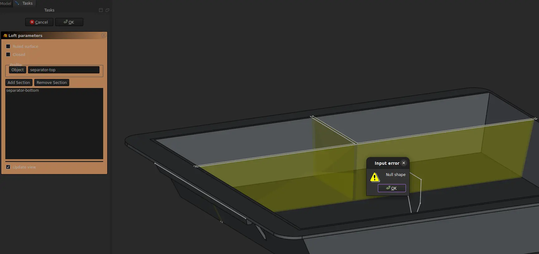
I have 1 major problem: I can't make a loft between my to sketches to create the separators. And I don't understand why.
Another point I do not fully understand is the construction lines. Should I use the External Reference or a Carbon Copy ? I don't really like the carbon copy as there's to much things displayed and sometimes I'm lost and don't see my original sketch anymore. For example, my bottom separator sketch must be linked somehow to my bottom box sketch, so if I change the position of the bottom of the box, the separator will adjust automatically.
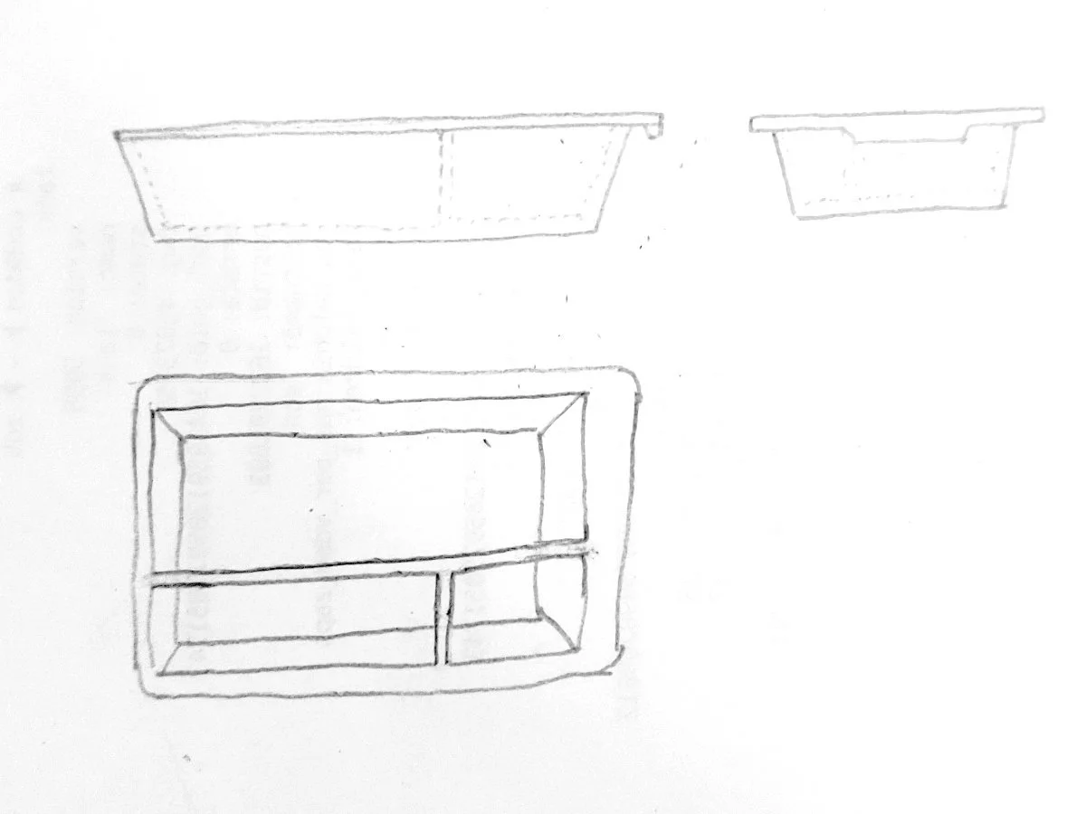
Here's an image of how the model should look (my previous iteration) https://imgur.com/a/H8on1MZ
and here's he file I'm currently working on. license CC0 1.0 (you can do whatever you want with it) https://drive.google.com/file/d/1WSgCSVhF1Io7ynhOXDkcO1hc8piln_mg/view?usp=sharing
-
How would you make this tray?


I'm new to freecad, so far I made it this way :
Sketch a rectangle for the top surface, pad it, add filets for the corners. Then select to bottom face, make a new sketch, another rectangle, then a datum plane 40mm below, sketch another smaller rectangle, and make a loft between the two to create the bottom of the tray.
Now for the hole I made a rectangle on the top face and made a pocket with an angle.
Downside of this, the thickness of the walls is not equal. Ideally I'd like a 1.5mm thickness everywhere. And I'm not really sure how to proceed to make the separators inside the tray.
What is the most efficient way to do it? thanks
-
FreeCAD 1.0/Ondsel 2024.3 Release Timeline?
Anyone aware of a target date for when FreeCAD 1.0 and/or Ondsel 2024.3 will be released?
Background:
I'm coming from using onshape, looking for a local opensource alt. After researching freecad (and forks) it seems if I was to start learning now, I'm in for a significant shift in workflow when 1.0 releases.
In its current state I'd lean towards ondsel.
Kind of putting off the switch till one or both implement the topo naming fix, and the other major ui changes for mainline, so I don't need to learn two different workflows.
But I'm getting antsy and want to get learning soon.
-
Does FreeCAD support 3D scans with color?
I am trying to design a simple case for a laptop motherboard, and thought to get around the distortion happening with my pictures by taking a 3d scan of it with Kiri Engine.
Everything looks fine in the preview of it and everything, but when I import the OBJ into FreeCAD it is just grey and I can't distinguish the mounting holes from the rest of the board.
Thanks in advance
-
CAD "best practices" that happen to avoid the toponaming problem?
Hi c/FreeCAD, totally newbie here! I'm having a ton of fun learning FreeCAD, but I have a small question. I know the toponaming problem is going away soon, and maybe that makes this kind of irrelevant, but I'd still like to know.
Sometimes when I'm watching or reading guides on avoiding the toponaming problem, the person will say something along the lines of: "actually this technique is also more professional/proper/correct anyway, real engineers do it this way." Basically that the methods that avoid the problem are also just best practices in general. But they always say that as kind of an aside, and I wish they'd say more! What makes those methods better? Does anyone have any suggestions for articles or videos about this?
For one example, there was one guide that suggested you should use a datum plane instead of referencing one of the object's surfaces. I understand the toponaming problem well enough to get why referencing a surface can cause it. However, the person in the guide used the same surface that would have been referenced, as the attachment point for the datum plane. Why does that not produce the same issue?
-
Just an early stage of modeling a sunglasses arm frame


I got sent a bunch of lenses that are too small for the old frames I have. I thought it might be fun to try 3d printing my own frame arms out of ABS.
Modeling a lens is a bit challenging, or I'm just a bit rusty with freecad. I need a way to wrap/unwrap/flatten the curve to create the contours. For my purpose here I can get away with a rough lens shape that is simply mirrored and lacks some of the complex curves. It just bugs me when I can't model it properly...
The lens is not uniform thickness. The center is 1.8mm thick while the edges where the arms mount are 1.4mm. I want to try and make a nose piece because this is the one part that fails on these cheap glasses.
Anyways, sharing just because I can.
-
Why is FreeCAD in the flathub beta repo just the stable release?
I wanted to try out the FreeCAD beta/nightly builds, and found on the website that you could get it from the flathub beta repo.
After installing though, it is just the same exact app? Did I do something wrong?
- blog.freecad.org FreeCAD gets a logo upgrade
Just in time for upcoming FreeCAD 1.0, the project got a major logo refresh. To get there, the design working group organized a popularity contest. Volunteers submitted 46 designs, over 1,500 commu…

- blog.freecad.org Vote for a new FreeCAD logo
There have been 46 submissions to the new FreeCAD logo contest. The user poll is closing on May 1 (this Wednesday). You can still pick your top 5 entries. The 5 winning submissions will then be sub…

There have been 46 submissions to the new FreeCAD logo contest. The user poll is closing on May 1 (this Wednesday). You can still pick your top 5 entries. The 5 winning submissions will then be submitted to the maintainers team for the final voting.
-
Help with exruding from one to another point on a sketch


In other cad programs i use two points of a sketch to extrude a feature. In freecad it does not seem to be possible. What are your recommended workarounds for that?
I would like to extrude the base not just from the face of the sketch, but from point 1 to point 2 on the side view sketch. This workflow proved very robust in other cad tools, but I cant get it work in freecad.
Thanks a lot in advance!
-
I just spent my entire weekend doing my Sketchup 8 keybinds. I just had to share.
And I'm curious if I could map my keys to make Freecad work this way. I don't know how many of the these tools don't exist in Freecad, but if I could one to one make a keybind that works for me, I might start using it instead of sketchup 8
But mostly, this is the because general CAD community on lemmy and I wanted to share, ciao!